
Edmund Pickering
Researcher, engineer, teacher
Conference paper
Publication Types:
Stress distribution in the mouse-tibia loading model using analytical approaches together with correction factors
INTRODUCTION:
The mouse-tibia compression model (MTCM), is the gold standard for studying bone adaptation due to mechanical loading in vivo [1]. Often, experiments are replicated in silico through finite element (FE) modelling, providing insights into the link between adaption and localised loading (i.e. stress and strain) [2]. However, FE models of the MTCM are rather complex and computationally expensive. An alternative is to use analytical models (i.e. continuum mechanics) [3]. However, the latter assume the fibula is negligible, thus overestimating tibial load. This work explores the validity of this assumption and proposes correction factors for the use of analytical models.
MATERIALS AND METHODS:
The tibia of a 16 week, female, C57BL/6 mouse was digitised via micro computed tomography (Skyscan 1172, 19 m voxel size). Both FE and analytical models were studied. The tibia was pin supported about the inferior articular surface. Load on the tibial head was represented by a point load at a given (x,y) location, 87 different load locations were investigated. For the FE model (ANSYS 19.2) a direct voxel to element meshing was used. For the analytical model, continuum-mechanics based beam equations were used (the fibula was neglected). An elastic modulus of 17 GPa and 10 GPa was used for bone and growth-plates respectively.
RESULTS & DISCUSSION
Figure 1 shows the proportion of load carried by the tibia, for different load locations. Studies suggest that in the MTCM, load is applied to the posterior edge of the condyles, thus approximately 88% of the load can be expected to be carried by the tibia. Comparison of the FE and analytical models shows error in the maximum axial stress to exceed 20% at the expected load location. Assuming skeletal similarity across C57BL/6 strain, we propose the load proportions from Figure 1 can be used as a general correction factor for the axial load in the analytical model. Through this correction factor, this error can be reduced below 10% at the expected load location.
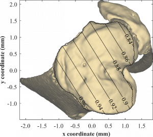
Figure 1: Proportion of load within the tibia for a given (x,y) load location.
CONCLUSION
Analytical models of the MTCM neglect the fibula. Dependent upon load location, it was found the fibula carries approximately 12% of the load, this can create sizable errors in the predicted stresses in the tibia. By correcting for the total load in the tibia, this error can be minimized.
REFERENCES
[1] A. Robling and C.H. Turner, Annu. Rev. Biomed. Eng., Vol. 8, pp. 455498, 2006.
[2] Sugiyama, et al., Bone, 43(2), 238–248, 2008.
[3] Wagner, et al., Journal of Biomechanics, 46(13), 2271–2276, 2013.
Where is the load applied in the mouse-tibia model? Insights through finite element modelling.
INTRODUCTION: The mouse-tibia loading model [1] has become the gold standard for investigating bone adaption and is a powerful tool in the exploration of interventions aimed at osteoporosis. In this, an in vivo loading regime is mechanically applied to the mouse tibia. Localised adaption of the cortical and trabecula bone can be measured. Often, this is replicated in silico through finite element modelling (FEM), providing deeper insights into the link between adaption and localised stresses and strain (a key component of Frost’s mechanostat [2]).
However, the FEM approach is problematic, as its predictions are highly dependent on how load is applied to the tibia. Differences in loading can results in large differences in the predictions of the FEM model. While some studies [3] have investigated this, the question of the where load is applied in the mouse-tibia model remains an open question. In this work, we seek to answer this question by investigating the relationship between load location and strain, comparing against experimental values.
METHODS: Female C57BL mice were used. Prior to experimentation, micro-CT slices were recorded. Following micro-CT, strain gauges were attached to the medial and lateral surface of the tibial diaphseal mid-shaft, proximal to the junction with the fibula, in line with the method used by De Souza [1]. The lower leg was mounted in a loading apparatus with the ankle and knee securely held by two cups. Loads were applied, up to 10 N, and the results strain gauge readings were recorded.
Using the micro-CT slices, the 3D geometry of the tibia was reconstructed through an in-house code. The volume was meshed through a direct voxel meshing approach where each voxel was transformed into an eight-node brick element. Nodes of the distal end were fixed. While the physiological loading at the proximal end is complex, it can be simplified to a single load at a representative location. A 10 N load was applied to the proximal end at selected coordinates. The load position was varied to quantify the relation between load location and strain measured at gauge locations. This is described in Figure 1a.
RESULTS AND DISCUSSION: The FEM modelling showed that the strains at each gauge location were highly dependent on the load location. This is significant as it demonstrates that failure to correctly identify the load location will results in erroneous prediction. To demonstrate this, Figure 1b-c shows the differing strain predictions for two different load locations.
This can be extended by modelling the gamut of potential load locations. In doing so, the effective load location can be ascertained, being the location with the minimum deviation between experimental and FEM strain values. This requires strain readings from a minimum of two gauges.
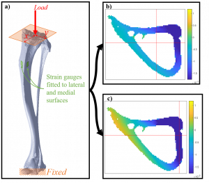
Figure 1: a) Schematic of the FEM model showing the variable load location, b-c) example strain predictions for two different load location (red cross-hair is a projection of the load location).
CONCLUSIONS: FEM modelling, coupled with in vivo data from two strain gauges can be used to determine the load location in the mouse-tibia loading model. Our results show that failure to correctly identify the load location will lead to erroneous results. We recommend that future works incorporate this technique to ensure valid predictions.
REFERENCES
- De Souza, R. L., et al, Bone, 37(6), 810–818.
- Frost, H. M, Anatomical Record – Part A Discoveries in Molecular, Cellular, and Evolutionary Biology, 275(2), 1081–1101.
- Poulet, B., et al., Arthritis and Rheumatism, 63(1), 137–147.
The super-element, stiffness-matrix approach to interrogate 3D intervertebral disc mechanics
INTRODUCTION
Finite element (FE) models of intervertebral discs (IVD) are inherently complex, requiring multiple tissue parameters to be defined for tissues which can be difficult to characterise experimentally. Due to this complexity, understanding how each parameter combines to produce the overall mechanics of the IVD is challenging. To overcome these challenges we used the super-element approach to provide a novel means of interrogating the IVD mechanics. Of particular interest in the current study, was the coupled, three dimensional (3D) mechanical response of the lumbar spine IVD and to what extent the 3D IVD stiffness is reliant upon the collagen fibre network.
METHODS
A physiologically realistic FE model of the L1-L2 IVD was developed. Geometry of the IVD represented the NIH Visible Human Project, Visible Man. Figure 1 shows the geometry and mesh of the IVD. The nucleus pulposus was modelled using 3D hydrostatic fluid elements, the annulus fibrosis ground matrix with 3D solid continuum elements, and the collagen fibres with tension only rebar elements. The rebar elements were embedded at ±30° to the transverse plane of endplates, to represent the alternatively angled collagen fibre network. Collagen fibre spacing and cross-sectional area was based on [2]. The annulus fibrosis was treated as a Mooney-Rivlin hyperelastic material ( MPa, MPa) and the collagen fibres as linear-elastic (tension only, MPa). Further details of the FE modelling can be found in [1]. Nodes representative of the superior and inferior end plates where constrained to a single node located at the centre of the respective end plate (referred to as control nodes).
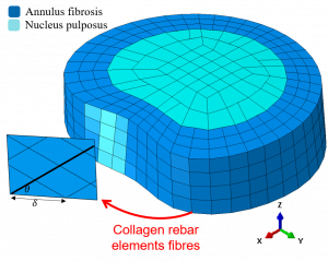
Figure 1: FE model of the IVD showing the annulus (with collagen fibre angle) and nucleus mesh.
In the super-element approach, degrees of freedom (DOF) of the FE model’s stiffness matrix are decomposed, retaining only the desired DOF. Here, a super element was constructed, retaining only the DOF of the control nodes. In this sense, the FE stiffness matrix can be simplified to a stiffness matrix in terms of just the loads and displacements acting on the superior and inferior surfaces of the IVD.
To explore the power of this approach, a parametric study was conducted to determine the influence of model parameters on the IVD behaviour. This provides a very effective way of elucidating the contribution of each individual component. Three parameters were investigated; collagen fibre stiffness (250 to 500 MPa), collagen fibre angles (15° to 60°), and ground matrix stiffness (0.35 to 0.7 MPa).
RESULTS AND DISCUSSION
Through the results of the parametric study, it was demonstrated how the super-element, stiffness-matrix approach is a powerful tool for interrogating the IVD mechanics. The study further demonstrates how the stiffness matrix can be visualised, providing a powerful technique for understanding the complex coupled motions of the IVD. The parametric study were able to identify several key model features: (i) collagen fibre stiffness plays a significant role in transverse stiffness, but play a lesser role in axial stiffness; (ii) a clear coupling between axial and transverse motion was observed, which was not significantly affected by fibre stiffness; and (iii) collagen fibre angle has a significant effect on IVD stiffness in all directions and on motion coupling.
CONCLUSIONS
The super-element stiffness matrix approach allows direct extraction of the underlying stiffness matrix which is advantageous in exploring the complex 3D behaviour of the IVD. This method of stiffness matrix extraction has several direct applications including as inputs for musculoskeletal modelling, benchmarking for artificial IVDs, and providing a powerful tool for exploring the complex 3D behaviour of the IVD. This approach can be effectively extended to analyse other tissue behaviour, such as the functional spinal unit.
REFERENCE
- J Little, Computer Methods in Biomechanics and Biomedical Engineering, 11, 95-103, 2008
- Marchand, F, Ahmed, A., Spine, 15(5), 412, 1990.
Impact of fuel oxygen on morphology and nanostructure of soot particles from a diesel engine
Diesel engines are often preferred over gasoline engines because of their fuel efficiency and reliability; however, there are significant issues around their environmental pollution which is controlled by emission regulations. To meet the ever more stringent regulations, reduction in diesel particle matter emissions can be addressed by minimising particle formation and by optimising particle oxidation in the combustion chamber and in the exhaust and diesel particulate filter systems. Soot formation and oxidation processes are the predecessors to the hysicochemical properties of diesel particulate matter and are characterised by morphology and nanostructure. These characteristics principally include primary particle size, fractal dimension, fringe length, fringe tortuosity and fringe separation distance. Thus, understanding of these characteristics is necessary for an efficient reduction of particle emissions from diesel engines. Furthermore, understanding these characteristics is important because they affect the aerodynamic behaviour of the diesel particulate matter in the exhaust system, diesel particulate filter systems, and the environment. This study aims to investigate the impact of butanol on morphology and nanostructure of soot particles from a 5.9 L turbocharged diesel engine at different engine loads. The oxygen content in the fuel was varied from 0% to 4.32% and 6.48% by using diesel, 20 and 30 % of butanol blends with diesel (Bu0, Bu20 and Bu30). The results indicate that the oxygenated fuels made by blending with butanol had a significant impact on the aerodynamic behaviour of soot particles. This could result in different lung deposition patterns and therefore different toxicity, as well as the change in the diesel particle filters’ filtration efficiency. As oxygen content increased, the corresponding nano-structural characteristics of fringe length and separation distance increased,
whereas fringe tortuosity decreased. The change of the nanostructure properties will further influence the diesel particle filters through the changes in the regeneration processes, and will therefore have a significant influence on implementing these fuels in modern diesel vehicles.
Worked example videos as a valuable blended learning resource in undergraduate engineering units
Abstract
Context
Within many maths-heavy (MH) undergraduate engineering units (UEU), teaching teams rely on written worked-solution documents to assist students in bridging the gap between tutorials and self-directed study. However, these are limited in their usefulness as they are a passive medium and poor at communicating the ‘why’ required for deeper understanding. Alternatively, worked-example videos (WEVs) involve an instructor demonstrating a solution while discussing the underlying strategies being employed. The audio-visual medium encourages increased interaction with the content, promoting cognitive processing and improving the quality of student learning. Limited studies have investigated the potential for WEVs as high-quality blended learning resources in UEU. Better understanding of WEV impact could lead to their widespread use in the blended learning transformation.
Purpose
To explore the impact of WEVs in MH-UEU by investigating student-video usage, interaction, and attitude, and the resultant effect on perceived academic performance.
Approach
WEVs were produced weekly for two MH-UEU at the Queensland University of Technology. Student engagement, perceived academic performance and attitude toward the WEVs were evaluated using a mixed methods approach incorporating viewership data and an end-of-semester survey. The study comprised 1,713 students across five cohorts over three semesters.
Results
Students engaged significantly with the WEVs with almost 24,500 views and 89 days of continuous viewing time across the five cohorts. Exam preparation was the dominant motivator for WEV usage. Approximately 90% of students used an active learning style when interacting with the WEVs, with many taking advantage of video controls like pausing, skipping and rewinding. This enabled students to work alongside the WEVs, using them to provide hints and verify solution processes, as well as concentrate on specific sections of the WEVs, thus individualising their learning to focus on areas they found challenging. The majority of students agreed WEVs improved their knowledge of the unit content, had the potential to improve their grades, and would be useful in other similar units.
Conclusions
WEVs are a valuable blended learning tool, capable of empowering student learning and enabling deeper engagement with problem solving tasks. Student interactions with the WEVs suggest that they are well-suited to MH-UEU where worked examples are an important learning tool.